74G clock buffer
Feedback from PotatoSemi:
I will like to share & discuss some technical information with you. When you use our clock buffer, we prefer that you can connect the entire clock buffer outputs without any open circuit. For example, when you use 3807 1 to 10 clock buffer, the best case will be 10 outputs connect to 10 similar loads. If in case that you only use 9 outputs, please add a dummy loading capacitor to the 1 left open output to make the termination. So the 10 output signals will switch about the same time. Any output signal without loading will switch much faster then the other output signal with loading. Much faster switching & delay time from open output signal will increase noise & jitter. The equal loading & same output trace length are important when you use clock buffers. Please let me know if you have any question or comment.
Comments:
I understand your comment and usually terminate unused outputs. However, I have wondered what the tradeoff is between equalizing loading and delta I noise.
If you leave the unused outputs open circuited, you will get a noise spike that is not coincident with the other channels. However, the current spike is mostly due to the overlap of PMOS/NMOS switching. If you add a load capacitance, you then add the current spikes from charge/discharging the load capacitance to the current spikes. How large are the two components?
Do you have any waveforms that compare the two situations?
Feedback from PotatoSemi:
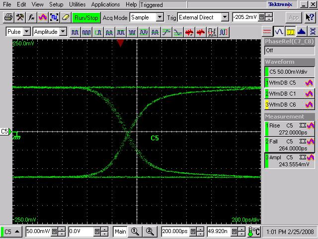
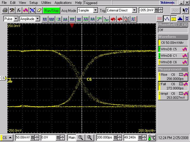
CMOS circuits have been used for over 50 years. All the CMOS circuit ICs have spike except potato chips. We have the technology to kill the spike so our products can run much higher frequency. You can see the comparison from the attached file. The left side is our 3807 with noise kill circuit. The right hand side is the normal 3807. All of them are running in same condition with 10 outputs switching at the same time. The output is driving 15pf loading. Now, you can see why the 3807 from other semiconductor companies can not run beyond 200MHz. Spike is the only reason. People also call them ground bounce or noise. Jitter is also related to the noise. They are all the same thing. We make our noise kill circuit perfect matching 8pf loading. If your loading is more far away, the chip ground noise will slightly higher. You can see the attached file for example. That output is driving 15pf loading. This is the reason we recommend our customers to add 8pf termination capacitor to the open output. This termination capacitor is only good for our GHz CMOS output circuit. Termination capacitor is no use to the regular CMOS outputs. This is just like what you said. They are going to be noisy anyway which does not matter you add the capacitor or not.
Comments:
Thanks for the information. In my specific application, I am driving a 50 ohm transmission line with an AC coupled 50 ohm termination. Do you still recommend using the same load as a dummy termination for unused outputs?
Feedback from PotatoSemi:
Yes. I still recommend adding 8pf dummy termination for unused outputs. Our noise kill circuit will work anyway which does not matter the loading is 0pf or 15pf. The 8pf dummy is only for the fine tune. Of cause, the best scenario is no dummy output. All the dummy outputs will waste power..